Passive Power Quality Solutions
We take the guesswork out of what Power Quality solution you need.
At GreenVolt Power Quality Solutions, we retain the lost art of sizing and designing passive solutions.
Constant Voltage Transformers (CVT)
CVTs provide stable, isolated voltage for sensitive equipment, reducing sags, noise, and disturbances across your loads.
Low-Cost Passive Mitigation
Our engineers design and specify the right solution for your site. Not every application site needs PFC or an AHF. Our first‑principles approach ensures you’re never sold equipment you don’t need.
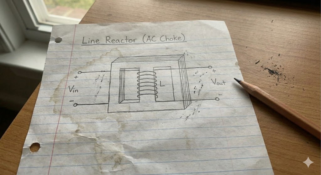
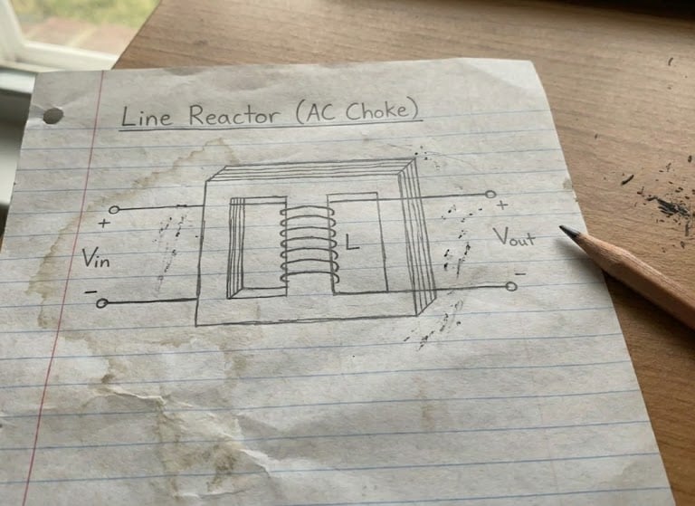
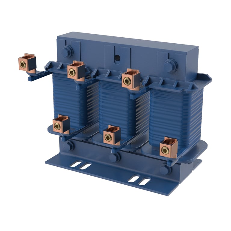
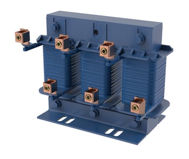
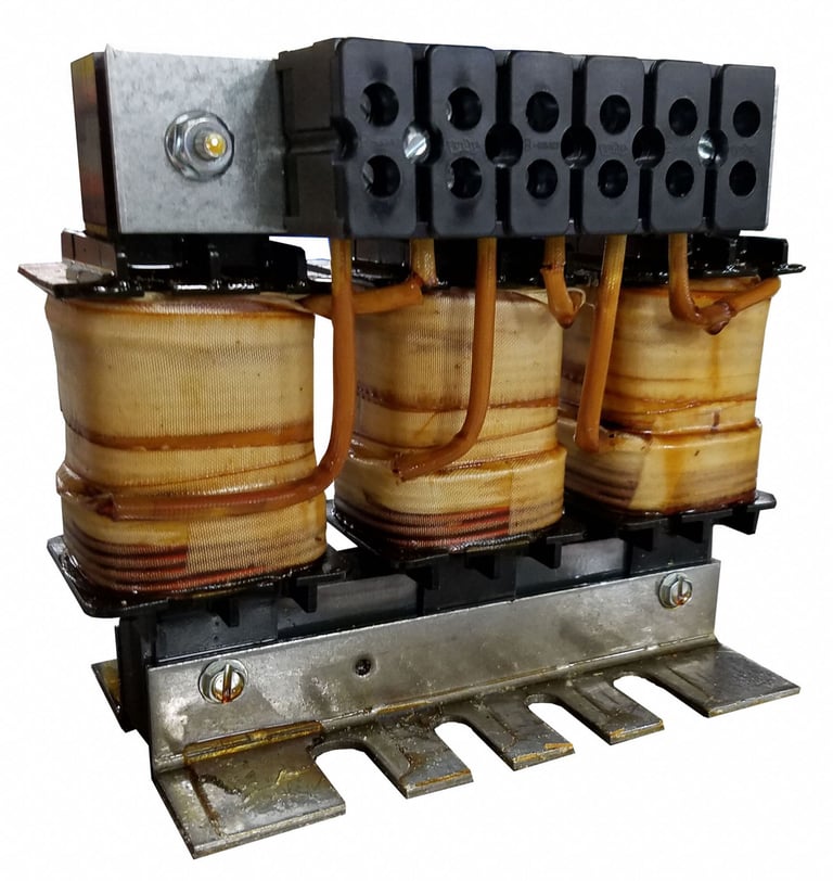
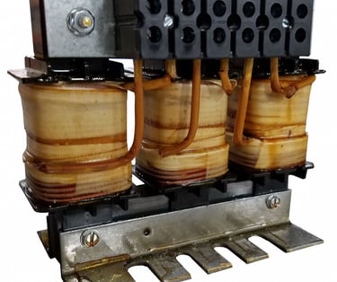
Reactors (Line/Load)
Line/load reactors add series impedance to smooth current waveforms, reduce voltage spikes, and protect drives from network-induced stress.
Passive Harmonic Filters (PHF)
A PHF is an electrical device, consisting of inductors, capacitors, and resistors, that creates a low-impedance harmonic current path.
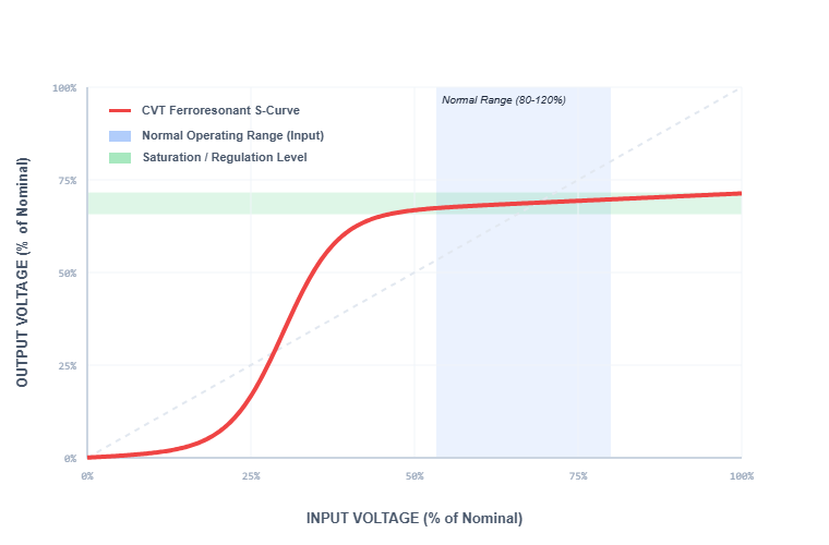
The CVT operates in the magnetic saturation region. When the iron core of a transformer is in saturation, relatively large changes in winding current results in very small changes in magnetic flux.
Winding current and magnetic flux are proportional to the input and output voltage, respectively.
This means that relatively large changes in input voltage result in small changes in output voltage, thereby acting as a voltage regulator.
Constant Voltage Transformers (CVT)
How does a CVT work?
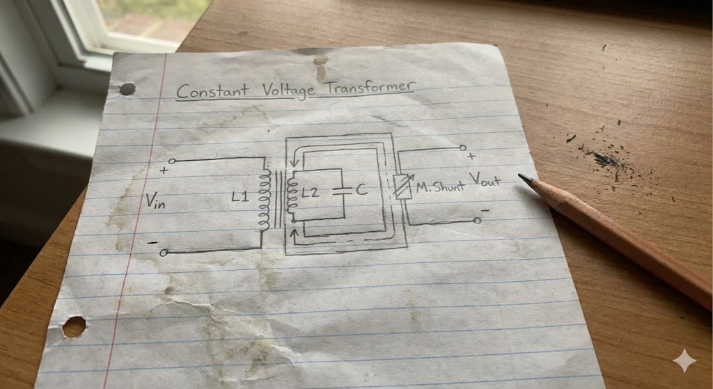
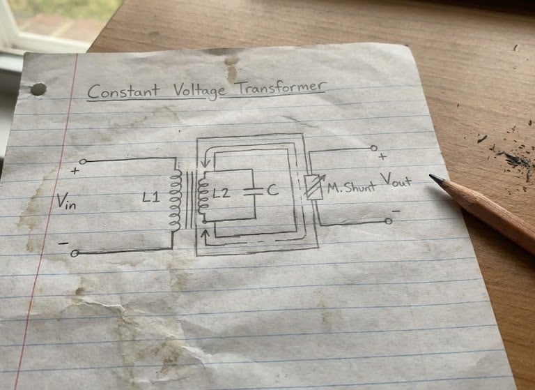
A Constant Voltage Transformer (CVT), or ferro-resonant transformer, is a specialised transformer that provides a stable, regulated output voltage despite significant input voltage fluctuations.
Using a magnetic shunt and a resonant capacitor, it utilises ferro-resonance to provide surge protection, noise filtering, and galvanic isolation.
Ideal for sensitive electronic equipment that has a narrow voltage supply range.
What is a CVT?
Comparison to Transformers (Linear)
Operation in the saturation region has the disadvantage of poor electrical efficiency and yields higher levels of harmonic distortion than operating in the linear region.
Standard power transformers are designed to operate in the normal range (blue) where electrical efficiency is higher.
While standard power transformers have some minimal capacity for voltage regulation, their primary purpose is to transform voltage from one level to another with higher electrical efficiency.
Protect your imported and sensitive equipment from voltage instability.
We design and size CVTs for industrial, commercial and residential application.
Get a CVT suitability check and integration assessment from us.
Reactors can protect motors, VSDs and other sensitive electrical equipment and increase their reliability and life span by absorbing disturbances in the line current, preventing overvoltage trips, improving total power factor, and reducing nuisance tripping.
Reactors can also help reduce harmonic currents by adding impedance on the line, hence reducing voltage harmonics and ensuring compliance.
Line and load side reactors reduce available voltage to the input of the motor drive and to the motor respectively, and therefore important not to oversize the reactor.
It is known that placement of the reactor is a critical consideration as it may resonate with capacitors however, our engineers have the experience and knowledge to guide you on its placement.
Reactors
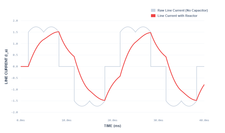
Line Side Reactors
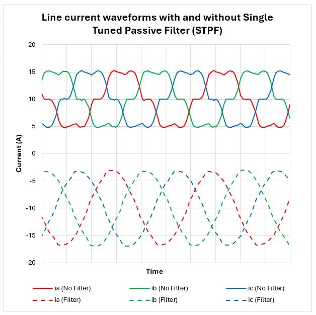
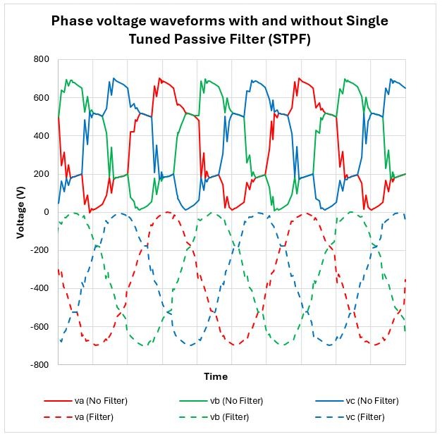
The line current into a six-pulse rectifier is shown. The twin peaks in every half cycle are due to dominating capacitive current.
The incorporation of a line reactor will tend to smooth the current and hence lower the peaks.
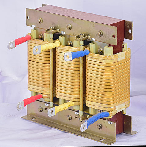
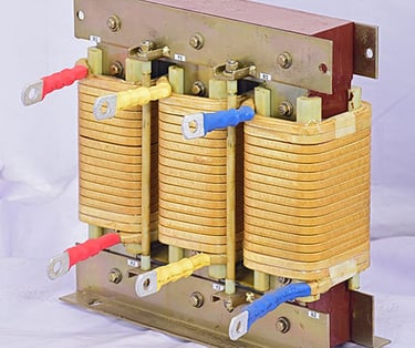
Load Side Reactors
Long motor cable runs and fast switching speeds can create reflected wave voltages and high-frequency noise that place excessive stress on motor insulation.
Load reactors are especially effective in these applications, as they slow the rate of voltage rise and dampen waveform transitions.
This protection helps extend motor life, reduce nuisance faults, and prevent premature equipment failure.
What can reactors do?
Seeing nuisance trips or overheating from specific harmonics?
We can engineer reactors that damp those frequencies without the cost of an AHF.
Get a reactor sizing assessment tailored to your site’s dominant frequencies.
The aim is to divert harmonic currents away from upstream impedance, to ensure a sinusoidal downstream voltage whilst keeping the fundamental current unaffected.
A PHF is an electrical device, consisting of inductors, capacitors, and resistors, that creates a low-impedance harmonic current path.
Passive Harmonic Filters (PHF)
PHF Mitigation Strategy
Seeing nuisance trips or equipment overheating from specific harmonics?
We can specify the PHFs that damp those frequencies without the cost of an AHF.
Get a PHF assessment tailored to your site’s dominant frequencies.
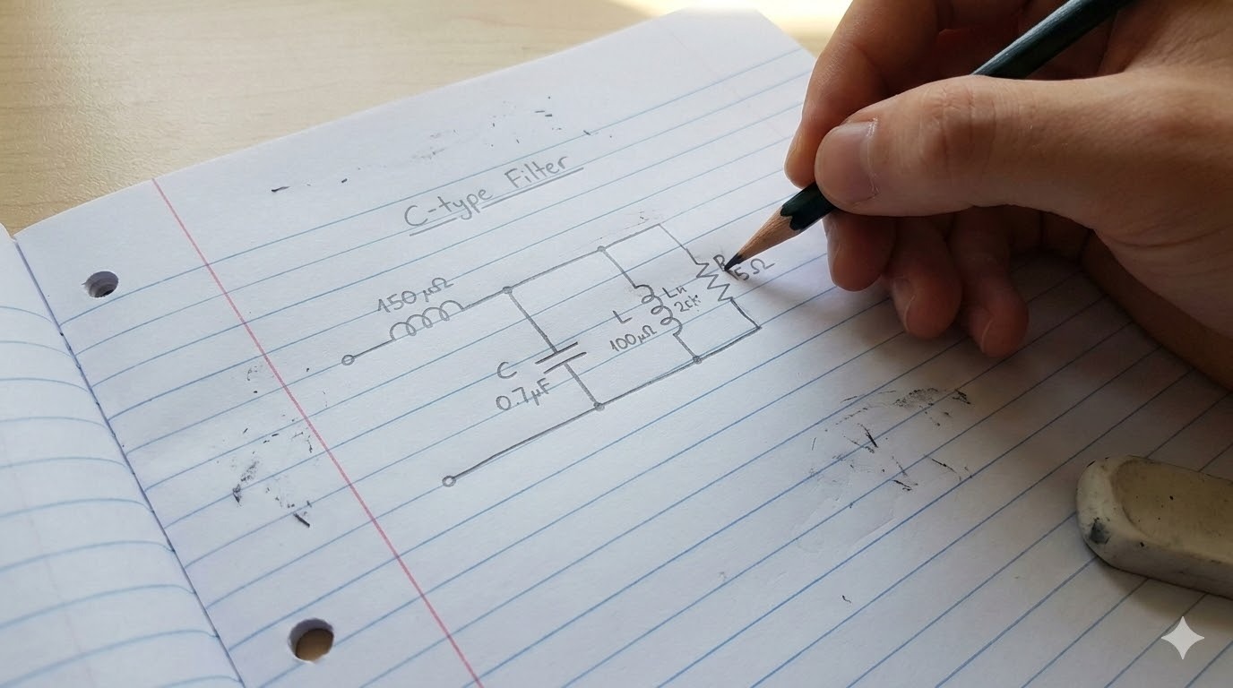
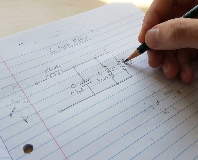
Common Filter Types
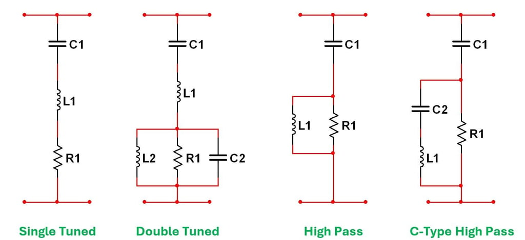

The four most common passive filter types utilised to address the mitigation strategy are shown and are often the first consideration prior to any Active Harmonic Filter (AHF).
The passive filters are installed in a shunt configuration and placed as close as possible to the offending load.
Combinations of the above filter types can be installed at the same location to ensure compliance limits are met.
The single and double tuned filters target specific frequencies whilst the high pass filters can accommodate a range of frequencies.
Wideband PHF
A Broadband Passive Harmonic Filter (BPHF) and or passive Wide Spectrum Harmonic Filter (WSHF) are designed to reduce multiple harmonic orders (such as the 5th, 7th, 11th, and 13th) produced by VFDs incorporating 6 pulse rectifiers.
Broadband filters use a combination of inductors, capacitors, and resistors (often in a "T" or similar LC/LCR configuration) to suppress a wide range of frequencies.
They are intended to reduce the THDi to within 5% at rated load and regardless whether the drive is equipped with a reactor or not (AC or DC).
Hybrid Filters - PHF and AHF
It is recommended to have some level of isolation (impedance) between PHFs and AHFs.
Most modern PHFs in use today are BPHF and incorporate significant inductance at both ends of the filter, and should provide the necessary isolation required; the input inductance also avoids resonance with the power system.